28 Years Factory SV-8800 Silicone Sealant for Insulating Glass to Egypt Importers
Short Description:
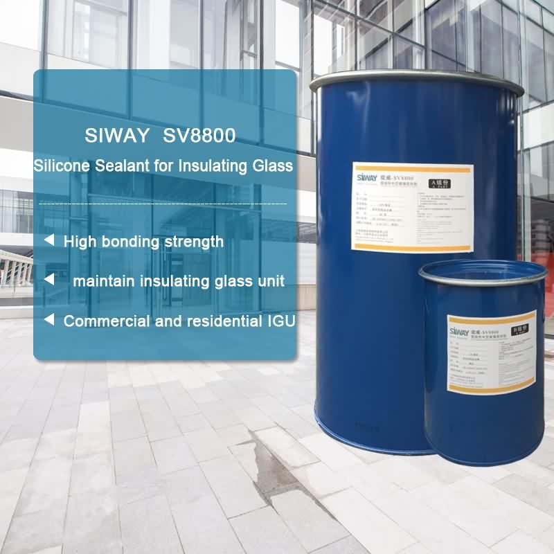
Description SV-8800 is two components, high modulus; neutral curing silicone sealant specifically developed for assembly of high performance insulated glass units as secondary sealing material. Where to use It is a two-component silicone that offers variable work life with high bonding strength to maintain the integrity of insulating glass unit, suits both commercial and residential IGU. Key Features 1. High Modulus 2. UV resistance 3. Low vapor and gas transmission 4. Primerless adhesion...
Our products are widely recognized and trusted by users and can meet continuously changing economic and social needs of 28 Years Factory SV-8800 Silicone Sealant for Insulating Glass to Egypt Importers, Our company will continue to adhere to the " superior quality, reputable, the user first " principle wholeheartedly. We warmly welcome friends from all walks of life to visit and give guidance, work together and create a brilliant future!
Description
SV-8800 is two components, high modulus; neutral curing silicone sealant specifically developed for assembly of high performance insulated glass units as secondary sealing material.
Where to use
It is a two-component silicone that offers variable work life with high bonding strength to maintain the integrity of insulating glass unit, suits both commercial and residential IGU.
Key Features
1. High Modulus
2. UV resistance
3. Low vapor and gas transmission
4. Primerless adhesion to coated glass
5. 100% compatible to SV-8890
Technical data sheet
| Test standard | Test project | Unit | value |
| Before curing——25℃,50%R.H. | |||
| GB13477 | Specific gravity(After mixing) | 1.33 | |
| GB13477 | Operating time | min | 20-40 |
| GB13477 | surface drying time(25℃,50%R.H.) | min | 80-188 |
| corrosivity | No | ||
| 7 days after curing——25℃,50%R.H. | |||
| GB/T 531 | Durometer Hardness | Shore A | 40 |
| GB13477 | The tensile modulus at 12.5% elongation | Mpa | 0.18 |
| The ultimate tensile strength | Mpa | 0.92 | |
| GB13477 | Elongation limit (fracture) | % | 150 |
Certification
GB-24266-2009;
Color
Component A(Base) – White, Component B(Catalyst)- Black
Package
1. Component A(Base): (190L), Component B(Catalyst) (18.5L)
2. Component A(Base):24.5kg (18L), Component B(Catalyst): 1.9kg (1.8L)
Shelf life
12 months
Note
If you want the TDS or MSDS or other details, please contact with our sales person.
You should check the valves at 500 – 600 miles, then every 6,000 miles after that.
Tools you’ll need:
10 mm socket
12 mm socket
Medium ratchet with short AND long extension
Big flat screwdriver or quarter
19 mm socket
Large ratchet
Flat feeler gauge
Torque wrench (one that works for low torques)
16 mm wrench (optional)
Need a Clymer manual? Check out https://www.clymer.com/ or https://www.youtube.com/user/ClymerManuals
Body work removal and installation: https://www.youtube.com/watch?v=Kki7S2RZBGQ
Remove the fan. The fan plug is mounted in a bracket on the frame – trace the wires, it’s easier than explaining. There are three 10 mm bolts. Two on the left and one near the center of the bike (right side of the fan) buried behind the radiator hose. The hose is pliable, push it out of your way. Use an extension. Unplugging the fan switch wire may also prove useful.
Marknet Valve Check / Adjustment Procedures: https://www.klr650.marknet.us/valves.html
I guess I lied. There is a link for the Clymers, but you still have to buy it: https://www.clymer.com/Book.aspx?bid=914&title=Kawasaki+KLR650%2c+1987-2006
Unplug the spark plug wire (leave the spark plug alone! What did it ever do to you?) and the temperature sending wire (right next to the spark plug). Remove the ignition coil. It has two wires going into the back, unplug them, then remove the 10 mm bolts holing it in place.
Remove the upper engine mount (I said I wasn’t going to to. *SPOILER ALERT* I tried to get the cover off for maybe 5 minutes to no avail. Then I gave in and took of the mount, the cover came out in about 10 seconds. Just do it). They are all 12 mm heads. Use the 16 mm wrench (not socket, like I said in the video… whoops.) to hold the plate “nut” from getting friendly with the engine.
Snip the wire ties. Get rid of the gas tank rubber doodads. Clean as much of the bike above the valve area as you can.
Take off the wire harness harness (two 10 mm bolts).
Remove the valve cover bolts, all four are 12 mm. The two on the right are straight forward. The back left takes some wire wiggling, and the front left takes a lot of wire wiggling. Store the bolts in a safe place in such a way that you know where they go when you need to put them back in. Mind their gaskets.
Valve stat sheet: https://www.klr650.marknet.us/valvclear.zip
Remove the valve cover from the left side of the bike. Be careful: the surfaces are precision machined, screw up and the chance of leaks goes up. BE GENTLE! Gentle like it’s your girlfriend / wife / whathaveyou.
Remove the two round plug on the left side of the engine. Use a big flat head screwdriver or a quarter. Use the 19 mm socket and large ratchet driver on the big hole and turn counterclockwise (the direction the wheels normally turn). There are three marks; you’re aiming for the third. It’s a straight tick mark with a T on right behind it. Watch the cam lobes. You’re at the “right” TDC (top dead center) when the tick mark by the T lines up with the lack of threads where the small cap goes AND the cam lobes all point away from each other. If you overshoot, take a breath, and spin the crank around TWICE. Watch the lobes if you’re wondering “why twice?”
Use a flat feeler gauge and check your valve shim clearances. Watch the video for the explanation.
Valve Shim Replacement: https://www.youtube.com/watch?v=R2d-V4udwaA
Use RTV Silicone Sealant and make a thin coat on both sides of the gasket. Put the gasket in place. Put the valve cover back in place from the left side of the bike. Again, BE GENTLE. You’ve made it this far, don’t fubar your precision machined surfaces now.
Replace the four cover bolts. Short on the left, long on the right. Tighten them evenly and carefully working your way up to 6 ft * lbs (that would be 71 INCH pounds).
Put the ignition coil back on, plug in the two wires on the back of it, plug in the temperature sending wire and put the spark plug cap back on the spark plug.
Put the fan back on (three bolts, 10 mm), plug it back in, put the plug back in its clip on the frame, plug the fan switch back in (bottom of the radiator).
Replace the wire ties that you snipped.
Replace the upper engine mount. All three bolts get torqued to 18 ft * lbs.
Replace the Body Work (link is up top).
Please rate and leave comments!
For a wealth of KLR 650 information, please visit KLR650.NET – Your Kawasaki KLR650 Resource!
If you decide to join, please use my referral link: https://www.klr650.net/forums/index.php?referrerid=17746
This video explains the use and maintenance of the Sealing Ring on Instant Pot IP-LUX/IP-CSG/IP-DUO series. More details and videos are at https://InstantPot.com.
The Sealing Ring is to device to seal the gap between the lid and the inner pot. Before every cooking session, please make sure the sealing ring is properly positioned to avoid steam leakage during pressure cooking.


